- Key Takeaways
- How a Flare Knockout Drum Works
- Critical Design Considerations
- Key Operational Parameters
- Enhancing Site Safety
- Optimizing for Alberta’s Climate
- The Unseen Economic Impact
- Conclusion
- Frequently Asked Questions
- What is a flare knockout drum?
- How does a flare knockout drum work?
- What are critical design considerations?
- Which operational parameters matter most?
- How does it enhance site safety?
- How should it be optimized for cold climates like Alberta?
- What is the economic impact of proper design and operation?
Key Takeaways
- A flare knockout drum eliminates liquids and solids from relief gas to safeguard the flare system and enable clean, stable combustion at the flare tip. Correct design and operation maximize site safety and environmental compliance.
- Inlet design, velocity reduction and gravity separation combine to reduce liquid carryover. This can be minimized by specifying correct inlet sizing, using internals such as demisters and monitoring vapor flow to avoid re-entrainment.
- Right-sizing the vessel for maximum gas and liquid rates is critical to reduce overpressure and carryover risks. Ensure material compatibility, select orientation to accommodate your layout and storage requirements, and comply with relevant codes and registrations.
- Monitor key operating parameters such as flow rate, pressure, and temperature with dependable sensors. Keep accurate records for commissioning, monitoring, and audits.
- Enhance safety with level measurement, alarms, auto drains, and flame arresters. Adhere to industry standards such as regular inspection, training, and maintenance to minimize failures.
Design for climate challenges with insulation, heat tracing, and appropriate low-temperature materials. Record performance, maintenance, and recovered liquids to safeguard assets, stay compliant, and optimize long-term economics.
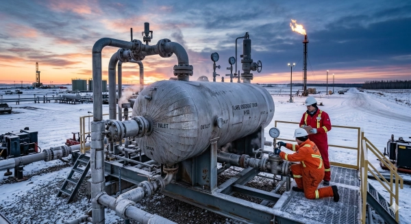
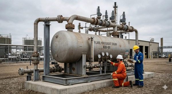
A flare knockout drum is a pressure vessel that removes liquid droplets and solids from relief gas prior to entering a flare stack. Utilized in oil, gas, and chemical plants, it stops liquid carryover which can lead to flame instability, smoke, or damage. They are commonly designed as vertical or horizontal drums with demister pads, inlet diffusers, and drain systems sized for maximum relief rates. Key specs include vapor load, droplet size cut, residence time, and sour or high-temperature service materials. Codes usually refer to ASME Section VIII and API guidance, with inspection on wall thickness, nozzles, and level controls. To help inform selection and design, the following sections summarize sizing approaches, layout options, internals, controls, and common traps with real-world examples.
How a Flare Knockout Drum Works
A flare knockout drum (KOD), known as a relief drum or flare scrubber, removes liquids and solids from a vented gas stream prior to the flare. Its job is to shield the flare system, reduce liquid carryover and maintain a steady, clean burn at the tip. As a primary node in the flare header, it provides safe gas disposal and helps comply with emissions regulations. Smart engineering and reliable performance increase plant safety and enhance environmental compliance.
1. Gas Inlet
The gas inlet nozzle directs incoming relief gas into the drum and establishes initial separation. Inlet velocity and entry angle induce droplet fallout. Excessive speed or misdirection can shear droplets and induce re-entrainment.
Typical configurations are tangential entry to encourage swirl and top entry with a downcomer to distribute flow. Side entry with diffuser is employed. Proper sizing must accommodate the worst-case relief rate and maintain low shear.
2. Velocity Reduction
Velocity decreases as the flow enters a larger cross-sectional area, allowing droplets to fall out by gravity. Slower vapor has less momentum, so the 300 to 600 micrometers droplets can settle, consistent with design targets in many codes.
Baffles, perforated plates, or vane packs aid in flow calming and straightening. Monitor vapor flow and liquid level. If vapor surge or foam occurs, separated liquid can be swept back up. Maintain a vesselless disengagement space above liquid, with a minimum of 0.9 m or three times the inlet pipe cross-sectional area.
3. Gravity Separation
Gravity is the primary means liquids exit the gas. Vertical drums accommodate small footprints, but horizontal drums provide longer residence times and more surface area for disengagement, aiding in high liquid loads.
Mist eliminators and demister pads remove fine droplets. Most flares desire droplets under 300 μm, while API RP 14J typically sizes for 400 to 500 μm. The dropout velocity Ud can be estimated with Ud equals 1.15 g dP (ρL minus ρV) divided by ρV CD. Tuned for these ranges, liquid carryover risk at the flare tip is lowered.
4. Liquid Collection
The vessel bottom is the sump for the hydrocarbon condensate and water. Capacity needs to be equal to slops, drains, and condensed liquid, depending on the anticipated duration of the event and the portion of the vessel’s hold that the liquid fills.
Use a level device, such as guided wave radar, for trustworthy readings during upset. A special outlet nozzle directs liquid to a sealed drain or slop tank for disposal.
5. Gas Outlet
The gas outlet transports scrubbed vapor to the flare stack and maintains good pressure control throughout the header. Nozzle placement strives to never suck in liquid, so it is often positioned high and distant from inlet turbulence.
A flame arrester at the outlet provides added flashback protection. The drum is usually constructed to the flare header design pressure of approximately 3.4 bar (50 psi) to withstand internal explosions and pressure waves.
Critical Design Considerations
Vessel Orientation
Horizontal drums fit long pipe runs and low headroom sites. They provide greater liquid volume for slugs and simplified internals access along a manway. Vertical drums minimize plot space, eliminate clutter and may ease foundations on confined pads or offshore decks. Orientation affects nozzle routing, lifting plans, and how crews access devices for servicing. A vertical vessel can be quicker to install on cramped sites. A horizontal drum can facilitate installation where crane radius is limited. Maintenance access includes clear platforms, side manways, and sufficient height for pull-out of demisters.
| Feature | Horizontal | Vertical |
|---|---|---|
| Liquid storage | Larger holdup; good for slugs | Lower holdup for same diameter |
| Footprint | Longer, low height | Small footprint, taller |
| Access | Side manways, easy demister pull | Top entry, ladder platforms |
| Install | Suits low headroom | Suits tight plots, offshore |
Material Selection
Select materials that are compatible with liquids, temperature, and design pressure. For sour gas or chlorides, use corrosion-resistant alloys such as 316L, duplex, or cladding. Carbon steel works for many sweet services; use a minimum of 1.6 mm thickness and note that stress at test and design becomes key above 204ºC. Low temperature toughness is crucial in Alberta winters; check impact test values at the minimum design metal temperature.
Avoid code and register. CRN’d vessels, ASME VIII, and site specs included. Where there is risk of explosion, most drums have a flare header design pressure of around 3.45 bar (50 psi).
Sizing and Capacity
Dimensions for gas and liquid peak About: Key Design Principles Determine liquid holdup in barrels full relief, normal retention time of 1 to 3 minutes by API gravity, more offshore, and emergency dump paths bypass valves. Keep sufficient vessel-free gas area above liquid, at least 0.91 meters or three times inlet pipe area.
Gravity settling involves designing vapor velocity low enough for drop-out. Many designs follow API RP 14J at 400 to 500 micrometers and check 300 to 600 micrometer limits. The typical horizontal slenderness ratio is 2 to 4. Undersized drums risk carryover and overpressure. Utilize vendor tools, API data, and validated droplet models.
Internal Components
- Inlet device: Diffusers or vane inlets spread flow, cut momentum and curb re‑entrainment.
- Mist eliminator: Mesh pads or high-capacity vanes trim droplets below about 300 micrometers. Score for fouling hazard and cleanability.
- Boot or sump adds stable holdup, clear interfaces, and tie-ins for emergency dump lines without control valves.
- Level control and measurement: Redundant radar or DP transmitters, high-high switches and proof testing secure continuous monitoring.
- Drain, sewer seal, and flare seal: Design sewer seal to at least 175% of maximum operating pressure to block backflow. Maintain demister pull space and inspection ports.
Schedule regular examination of pads, vanes, and inlets. Inspect for corrosion, fouling, and gasket seats. Ensure free gas area and vertical velocity following any service alteration.
Key Operational Parameters
Flow rate, pressure and temperature establish how a flare knockout drum is sized, constructed and operated. Precise, real-time measurements keep the vessel within design parameters and facilitate safe discharge. These parameters dictate orientation, shell thickness, metallurgy, internals, and safety devices. Capture all set points, ranges and alarms during commissioning and then trend them for audits and maintenance.
Flow Rate
Maximum gas and liquid rates determine vessel diameter, length, and orientation. For key operating parameters, use the critical velocity equation Vc equals K times the square root of ((ρL minus ρg) divided by ρg) to set permissible vapor speed, then work backwards to calculate vessel diameter. K equals 0.27 for vertical drums, but for horizontal units, use vendor guidance since K shifts with geometry and internals. Length is typically linked to liquid hold-up per API 521, with 20 to 30 minutes assumed for emergency relief sizing.
Flow data from transmitters on upstream headers and liquid drains monitor to verify the drum remains below its design rates. Install high-high flow alarms that connect to flare load shedding where permitted.
Variable operating rates can drive vapor velocity above target, retention time below plan and reduce liquid droplet removal. Most designs strive to eliminate 300 to 600 µm droplets. Some smokeless flares or close-firing burner tips require 150 µm, which can result in increased diameter or improved demisters.
Fit heavy duty flow elements, such as ultrasonic or averaging pitot for gas and Coriolis or magnetic for liquids, so operators witness real-time changes and tweak diversion prior to carryover.
Pressure
A knockout drum is a pressure vessel with a specified design pressure in kPa or bar, typically displayed with psig for operating. Verify that its rating is greater than the maximum credible header surge and downstream backpressure during relief.
PSVs and rupture disks offer overpressure protection. Size PSV setpoints under vessel MAWP. Use a rupture disk as secondary protection where fast action is required.
Check drum ratings versus flare system hydraulics at HAZOP and revalidate after tie-ins. Schedule internal and external inspections, thickness checks, and pressure tests per code and company standards.
Temperature
Process and ambient temperatures determine steel grade, corrosion allowance, and insulation. High temperatures could require high-temperature gaskets, seals, paints, and enhanced demister materials.
Cold service counts. For Alberta or other cold places, heat trace, insulate, or use heated enclosures and test low temperature toughness for shell and nozzles.
Monitor temperature via skin and organ sensors. Steady temperatures aid separation, maintain viscosity, and safeguard droplet removal effectiveness and residence time.
Enhancing Site Safety
Flare knockout drums remain a fundamental site safety layer in oil and gas locations. They prevent liquids and solids from hitting the flare tip, reducing the hazard of fire, explosions, and unburned hydrocarbon emissions. They assist in complying with international regulations, as nearly all standards require a knockout drum prior to a flare. Design for high pressure, corrosive fluids, and safety margins in accordance with ASME section VIII – pressure vessels and API 521 – flare design and relief handling. Good siting counts as well. Locate the drum to reduce thermal radiation that can age seals and instruments.
Preventing Liquid Carryover
Good phase separation keeps liquid hydrocarbons and water out of the flare header and tip. Oversized drums, typically horizontal vessels with a central inlet and gas outlet, decelerate the flow so droplets fall out. For certain sites, we have a three-phase drum to separate gas, oil, and water.
Liquid carryover can result in flame lift, burn-back and flare-tip damage. In worse cases, it can ignite fires in adjacent buildings or catapult liquid to the stack where it burns in a surge.
Improve site safety by employing dependable level measurement with redundant transmitters and high-high alarms. Include local flags for cross-checks and try them in operating conditions.
Provide automatic drains opening by level demand, such as strainers, block valves, and check valves. Connect the discharge to a closed, rated system.
Industry Standards
API 14C, API 14C SAC A.4.C.1, SAC A.4.C.5 for safety analysis and shutdown logic applicable to this, enhancing site safety. ASME Section VIII governs pressure-vessel design and fabrication, and API 521 guides relief loads, sizing, and layout for flares.
Following those standards goes a long way toward assuring equipment quality, legal compliance, and standard practice across sites and regions.
| Standard | Scope | Key Requirements |
|---|---|---|
| ASME Sec VIII | Pressure vessels | Design pressure, materials, welds, NDE, nameplate |
| API 521 | Flare/relief systems | Sizing, relief scenarios, radiation, knock-out volume |
| API 14C & SAC A.4.C.1/A.4.C.5 | Safety systems | Cause-and-effect, ESD levels, detection, alarms, testing |
How do you document compliance with material certs, weld records, hydrotest reports, and SIL/ESD proofs in audits and inspections?
Common Failure Modes
Common failure modes are liquid carryover, vapor velocity that overwhelms separation and breach due to corrosion or overpressure. Inadequate sizing or maintenance decreases residence time, lowers separation, and increases hazard.
Use diagnostics: differential pressure across mist eliminators, level-rate trends, acoustic or vibration monitors, periodic NDE on shell welds and nozzles, and flare radiation surveys after changes.
Maintain incident logs with both root cause and solutions. Items include operator training, proof tests, PSV set checks, and vendor service notes. Ruggedized testing and precise manufacturing tolerances reduce defects prior to commissioning.
Optimizing for Alberta’s Climate
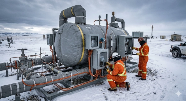
Flare knockout drums in Alberta endure long, cold snaps, high winds and heavy snow. Designs require winter-hardened hardware, low-temp materials and trusted heat management to maintain consistent and safe liquid removal while reducing flaring and venting. This connects to provincial objectives under the Emissions Management and Climate Resilience Act and continued actions to reduce emissions and conserve gas since 2000.
Winterization Needs
Heat tracing on liquid outlets, level bridles and drain lines prevents fluids from freezing. Add top-of-the-line insulation on tanks and lines to maintain skin temperatures above hydrate and wax points. Insulate instrument impulse lines as well, or employ heated, redundant transmitters. They help stabilize separation prior to gas hitting the flare, which promotes improved combustion. Solution-gas flare efficiency has been between 62 and 82 percent.
Package compact shelter or modular building for level instruments, pumps, and control panels. In high-wind corridors, a panelized enclosure with rated snow loads and floor heating prevents valves and seals from icing, reduces instrument failure, and simplifies maintenance access during blizzards.
Monitor temperature and fluid levels throughout the winter. Accommodate dual level instruments, such as guided-wave radar and differential pressure, high-high shutdowns, and heat-trace alarms. Tie these into SCADA so crews can see trends early at large flaring batteries, where the largest flared and vented reduction stills sit.
- Electric or glycol heat tracing with failover on thin lines.
- High-performance insulation with weatherproof jacketing
- Heated enclosures or skid buildings with ventilation
- Steam or hot-glycol jacketing for waxy or wet streams.
- Low-temperature-rated seals, gaskets, and lubricants
- Sloped piping, drain points, purge ports to remove liquids
- Instrument winter kits and freeze-protected sample taps
Material Toughness
Choose CSA/ASTM low service temperature steels (carbon grades LTCS – Charpy tested – or suitable nickel alloys when fluids are sour). Cold weather makes brittle fracture more probable. Using standard carbon steel without demonstrated toughness can risk vessel failure in a sudden cold soak or wind chill.
Check material test reports for minimum design metal temperature, impact values, and weld procedure qualifications less than or equal to anticipated ambient lows. Alberta sites can experience −40 °C, so determine MDMT accordingly with corrosion allowance and cyclic loads in mind. NDE, strong welds, and PWHT where required minimize crack starters. Coatings and linings need to be low-temperature rated so as not to embrittle, particularly with condensates prevalent near heavy-oil and bitumen operations, which have been responsible for increased venting in areas like Lloydminster since 2005. Tough materials and sound fabrication reduce leaks and unplanned vents, enabling emission reductions where 7.3% of sites still account for 39.4% of vented gas and the industry has topped 8 Mt CO2e in previous inventories.
The Unseen Economic Impact

Well-run knockout drum trumps flare penalties. It protects assets, prevents liquid carryover, promotes compliance and increases product recovery, which minimizes downtime and waste and maximizes cash flow.
Asset Protection
Knockout drums protect flare tips, pilots and headers from corrosive liquids that would erode alloys, clog nozzles and snuff the flame. This is where irrecoverable residues from oil and gas streams are trapped and, at high pressure, liquefied. This is a costly nuisance if sent up the flare stack.
Asset life increases when liquid-induced damage is excluded from hot zones. By preventing carryover, you prevent thermal shock, cracking, and soot buildup that prompts tip changeouts and stack repairs. In plants that rate 3.4 bar (50 psi) MAWP to resist an explosion, design margins and code-compliant fabrication add cost up front but reduce lifetime spending by avoiding catastrophes.
Establish an inspection schedule, drain checks, seal inspections, corrosion mapping and relief path proof tests. Accurate level measurement is critical. High pressure and condensate-rich service complicate matters, so choose instruments designed for condensation, foam and density variations, and verify them. Maintain a transparent record of asset condition, calibrations, and maintenance history. Insurers frequently price premiums and claims on the quality of documentation, which can tip the total cost of ownership.
Regulatory Fines
Non-compliance with environmental and safety rules ushers in large fines, consent decrees and forced shutdowns. Agencies and climate modelers now want credible flare combustion efficiency and destruction removal efficiency data to quantify methane in global inventories, connecting site practices to unseen economic impact.
Dependable measurement and record-keeping is not a luxury. Employ measured flow, heat content, steam-assist rates, and measured destruction, not sloppy, hand-waving estimates. You get silly policies that still cost a ton of money. Automated monitoring—gas analyzers, thermal cameras, and stack sensors—provides constant proof of performance and initiates action before limits are breached. Proactive management reduces the likelihood of fines, curtailments, and unplanned flaring.
Product Recovery
Efficient separation allows sites to capture valuable hydrocarbon liquids from relief gases instead of flaring them. This process converts sporadic upsets into marketable products or feedstock. Monitored recovery volumes, combined with loss reports, inform setpoint adjustments and valve repairs that increase throughput and reduce waste.
Cutting-edge drum designs, combined with new flare tips and combustion equipment, increase efficiency and decrease emissions, generating direct savings in fuel consumption and indirect savings in carbon liabilities. With level instruments reading true under condensation and pressure swings, operators can push closer to optimum hold-up without trips. This increases both safety and margins.
Conclusion
A properly sized flare knockout drum rewards. The unit reduces liquid carryover, maintains flare stability, and decreases risk. It’s good engineering and frequent inspections that produce that outcome. Good seals, short run pipe, and clear drain paths keep the system tight. Proper level control and heat tracing matter in cold sites like Alberta.
To schedule upgrades, begin with actual information. Monitor flare gas flows, liquid loads, and weather fluctuations. Use that to determine drum volume, inlet device, and boot size. Tie regulations and local ordinances into each selection. Little holes become big holes in your wallet.
Need a rapid next action? Map your existing drum restrictions. Then schedule a couple of cheap fixes, such as a new mist pad or improved heat trace. Contact me if you need a quick recap.
Frequently Asked Questions
What is a flare knockout drum?
A flare knockout drum is a vessel that separates out liquids and solids from relief gas prior to flaring. It stops liquid carryover, safeguards the flare stack and minimizes emissions. It is the industry norm in oil, gas, and petrochemical locations for secure, dependable flaring.
How does a flare knockout drum work?
Gas in, flow reduced, gravity separates liquids and droplets. Internals like demisters and baffles enhance separation. Scrubbed gas goes out to the flare. The accumulated liquids drain to a secure system. Correct sizing provides sufficient residence time for separation.
What are critical design considerations?
Inlet moment, residence time, droplet size distribution, liquid load, temperature and corrosion allowance, etc. Designers think about internals selection, nozzle layout, drainage and maintenance access. It meets API 521 and site standards.
Which operational parameters matter most?
Monitor inlet flow rate, pressure, temperature, liquid level and DP. Keep an eye on drain rates and demister performance. Maintain flares and knock out drums, and keep alarms and trips calibrated. Stable operation safeguards the flare and reduces emissions and liquid carryover hazards.
How does it enhance site safety?
It prevents liquid slugging and flare tip damage. It cuts down on flame instability and thermal radiation spikes. It restricts hydrocarbon emissions and reduces fire hazard. Dependable separation contributes to keeping flares safely burning during upsets and emergency situations.
How should it be optimized for cold climates like Alberta?
Insulation, heat tracing, and low temperature materials. With sloped drains, freeze-protected boots, heat-traced level instruments. Check pour points and hydrate hazards. Designed for cold starts and viscous fluids. Winterization maintains separation and drainage dependably.
What is the economic impact of proper design and operation?
Well-designed cuts maintenance prevents flare tip failures and minimizes unanticipated shutdowns. It reduces fuel gas losses and environmental fines. Reliable performance not only extends equipment life but improves compliance, decreasing total cost of ownership over time.
Not what you were looking for? Explore more equipment solutions from Benoit Rentals Ltd to learn about reliable oilfield rentals that support safe and efficient wellsite operations.
Want to learn more about the equipment and processes used in oil and gas production? These trusted resources offer helpful background information:
Flare Stack Systems Used in Oil and Gas Facilities
Oil and Gas Development Information from the Government of Alberta