- Key Takeaways
- How Test Separators Work
- Key Selection Criteria
- Common Test Separator Types
- Alberta-Specific Considerations
- The Mobility Decision
- Why Expert Partners Matter
- Partner with experienced equipment providers to access high-quality, fully compliant test separator packages tailored to your needs.
- Rely on expert support for equipment selection, installation, commissioning, and ongoing maintenance.
- Benefit from proven track records in delivering reliable, accurate measurement and safe separation under Alberta oilfield conditions.
- Encourage operators to prioritize expertise and service quality when sourcing test separators for critical well testing operations.
- Conclusion
- Frequently Asked Questions
- What is a test separator and why is it used?
- How do test separators work?
- What criteria should I use to select a test separator?
- What are common types of test separators?
- What should operators in Alberta consider?
- When should I choose a mobile test separator?
- Why work with expert partners for well testing?
Key Takeaways
- Well test separators separate well fluids into gas, oil, and water for metering and sampling. Efficient separation is achieved through internals like inlet deflectors, weirs, and mist eliminators backed by accurate metering and controls.
- Inlet diversion slows velocity and balances flow to minimize turbulence and re-entrainment. Choose proven devices like diverter plates, wave breakers, or vane packs and size to anticipated flow.
- Momentum change along with gravity settling cooperate to separate phases without emulsification. Tune vessel orientation, retention time, and sectional area. Level control is important for stable performance.
- Mist extraction safeguards downstream machinery and guarantees gas purity. Define coalescers or demisters with proven removal efficiency and check performance at commissioning.
- Proper discharge metering facilitates dependable allocation and reservoir management. Calibrated meters on each outlet, level controllers, and shutoff valves are included in the checklist for instrumentation check.
- Choose separators based on fluid volume, pressure rating, and separation type for well conditions and unit mobility requirements. For Alberta and similar regions, factor in extreme weather, sour service, heavy oil, and select skid or trailer packages accordingly with compliant materials and safety systems.
A test separator breaks a test suite into smaller sets so they run in parallel or sequentially with reduced waiting. Employed in unit, integration, and end-to-end runs, it distributes load across nodes and maintains stable run times as code scales. Popular strategies encompass file-based splits, historical timing, and dynamic balancing using information from previous runs. Teams rely on it in CI pipelines to reduce build time, eliminate flaky bottlenecks, and shorten feedback loops. Most configurations assume timing data in seconds, resource tags, and retry rules that steer clear of hot spots. To provide concrete steps, the guide below outlines key techniques, trade-offs, and advice to optimize splits for speed and consistent results.
How Test Separators Work
Test separators take one commingled well stream and separate it into gas, oil, and water so that each phase can be measured independently. Through staged steps of flow diversion, momentum drop, gravity settling, mist extraction, and controlled discharge, along with precise instruments, the vessel delivers reliable well-by-well rates for allocation, diagnostics, and reservoir control.
1. Inlet Diversion
Inlet deflectors or baffles turn and spread the entering jet so velocity decreases and flow fills the vessel cross-section. That initial redirect moderates shock loads, balances residence time and prepares clean gravity separation.
Less turbulence means fewer droplets get sucked back into the wrong phase. It reduces re-entrainment and foaming, which in turn decreases chemical usage and unscheduled cleaning.
Proper inlet design enhances separation, minimizes sand impingement, and minimizes internal wear. Typical separators are diverter plates, wave breakers, vane packs, and impact baffles.
2. Momentum Change
Separators reduce the velocity so that gas escapes from liquid and bulk solids prior to fine polishing. Lower velocity reduces shear that creates stubborn emulsions, which preserves heat and demulsifier downstream.
Horizontal vessels provide a longer path and larger surface area for momentum loss. Vertical vessels promote compact footprints and rapid gas separation under high gas-oil ratios.
Comparison of momentum methods:
- Horizontal: inlet diverter and long settling section are best for slug dampening.
- Vertical: Tangential entry and calming section are ideal for high gas draw-off and small pad.
- Hybrid internals: vane packs and calming baffles are best when flow swings widely.
3. Gravity Settling
Once calm, density drives the split. Gas rises, oil forms the middle layer, and water sinks. Sufficient retention time and cross-sectional area are critical to the rise and fall of droplets.
Weirs and interface baffles retain stable oil and water layers and prevent short-circuiting. Watch glass level gauges, differential level transmitters and interface controllers keep targets steady.
4. Mist Extraction
Mist extractors pull fine liquid from gas before it leaves. Vane sets, mesh pads, and high-capacity demister elements coalesce droplets to reach gas specs and protect compressors and meters.
Type and rated removal, for example, 99% of 5 µm, is matched to anticipated gas load and fouling hazard.
5. Fluid Discharge
Oil, water, and gas are discharged via separate outlets with shut-off valves and isolations. Each line uses fit-for-purpose meters: orifice plates, ultrasonic meters, or turbine meters, with pressure and temperature taps for energy correction.
Level controllers and high-high shutoffs avoid carryover and trips. Package checklist: flow meters per phase, pressure/temperature transmitters, level instruments (glass and electronic), control valves, relief devices, sample ports, and calibration ports.
Key Selection Criteria
So, look at fluid capacity, pressure rating, separation type and mobility first. Then verify vessel specifications, internals and instrumentation to standards and your site limits. Match to wellhead conditions, flow rates, crude characteristics and solids. Construct a concise needs table to rate vendors based on musts, would likes and risks.
Fluid Capacity
Size for both peak and turndown. Determine maximum and minimum flow rates of oil, gas, and water the test separator must meter within target uncertainty. Put in surge margins from start-up, choke moves, and cleanups.
Design for brittle streams. Take into consideration liquid slugs, sand load, wax or asphaltene drop-out and emulsion risk. Describe internals such as inlet cyclones, sand boots, and coalescers as applicable.
Vessel volume and residence time at the full rate range strive for steady level control and gas separation without carry-over and carry-under. Check control valve Cv and meter ranges coincide within the same envelope.
- 50 to 250 cubic meters per day of oil and 10,000 to 80,000 cubic meters per day of gas: single-well delineation in Alberta tight plays.
- 250–1,000 m³/d oil, 80,000–300,000 m³/d gas: multi-rate tests on light oil and gas-condensate wells.
- 1,000 to 3,500 cubic meters per day of oil and 0.3 to 1.0 million cubic meters per day of gas: high-rate pads and SAGD test loops.
- Water cut ranging from 10 to 95 percent and sand up to 0.5 percent mass requires adding sand handling and wax mitigation for winter service.
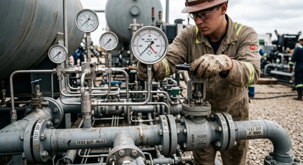
Pressure Rating
Established by shut-in wellhead pressure, anticipated reservoir drawdown, downstream constraints, design factor and corrosion allowance. Verify ASME Sec VIII compliance and material traceability for sour service NACE compliance. Model pressure drop across the separator and internals, because high Δp can cut production, shift phase behavior and increase safety risk. Minimize Δp while maintaining measurement integrity.
| Application | Typical MAWP (bar) |
|---|---|
| Onshore sweet | 35–69 |
| Onshore sour (H2S) | 69–103 |
| Offshore platform | 103–172 |
| HP/HT or deep gas | 172–241 |
Separation Type
Choose two-phase for dry gas wells or early screening, three-phase for oil-water-gas metering, and four-phase when free sand or condensate stabilization requires its own stream. For complex fluids, incorporate electrostatic grids, compact cyclonic stages, or heated coalescers to satisfy test objectives and reservoir monitoring strategies. In Alberta, three-phase fits most oil tests, and four-phase aids sand-prone or waxy streams.
Two-phase: simple, low cost, and no water cut data. Three-phase: balanced data set, more internals and tuning. Four-phase: best solids and heavy-end control, larger footprint and higher cost.
Common Test Separator Types
Test separators divide wellstream flow for measurement in controlled, often low-pressure, low-temperature environments. Operators select two-phase, three-phase, or four-phase units according to fluid type, water cut, sand load, and testing objectives. They designed the common test separators in vertical, horizontal, and spherical shells, with modular internals that can be customized. A handy side-by-side chart of type, key features, and typical uses helps teams align on selection prior to field deployment.
Two-Phase
Three-phase separators divide gas from a mixed liquid flow where oil and water exit jointly. They suit wells with low water cut, gas-lift pilots and early appraisal where gas-liquid rates, GOR and fundamental stability are the main requirements.
They’re small, cheaper, and quick to deploy, so they’re ideal for skids, trucks, and offshore well test packages. They are popular for short-term tests, DSTs, GCTs, geothermal steam-liquid split, and tight gas cleanups. They’re low pressure and temperature, sometimes connected to one or two stage lab flashes to verify gas solubility and oil FVF near bubble point. Periodic tests channel a well into the separator and test wells with a single phase flowmeter; information powers allocation and well monitoring.
Three-Phase
Three-phase separators produce clean gas, oil, and water streams to enable rates and water cut tracking. They are common in crude test separators where water is material, such as mature fields or offshore platforms with water handling and heavy oil with stable emulsions.
They require good interface level control, coalescers or plates, and reliable density, conductivity, and temperature instrumentation. Thanks to its internals and residence time, they optimize allocation, facilitate reservoir analysis, and allow water quality inspections for reinjection or release. They minimize lab bias by slashing carry-over ahead of one- or two-stage flashes.
Four-Phase
Four-phase separators incorporate solids removal to separate gas, oil, water, and sand. Wells with high sand or scale, unconsolidated reservoirs, and post-frac wells are best served by protecting downstream chokes, meters, and heaters.
They commonly incorporate sand jetting, desanders, baffles and dedicated sumps with purge lines. Horizontal shells provide room for settling and servicing. Vertical options accommodate small cushions. Best use cases include early production facilities, flowback, heavies with fines and remote tests where cleanouts are expensive. Choice depends on solids rate, particle size and safe disposal regulations.
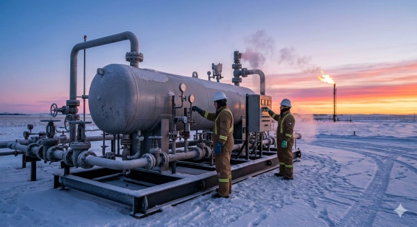
Alberta-Specific Considerations
Alberta’s oil and gas footprint is dense, cold and highly regulated, so test separator decisions have to accommodate harsh weather, sour fluids, heavy oil and local regulations. Think rugged build, field-true instrumentation, and complete compliance with provincial and industry standards from AEP oil-water separator requirements to CAPP-inspired approaches. Create a checklist that aligns equipment specifications with low temperatures, H2S thresholds, heavy crude characteristics, disposal regulations, and geological considerations.
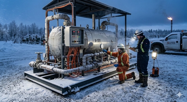
Extreme Weather
Separator vessels, piping and instruments must be rated for -40 °C service and outdoor duty. Seek out low-temp impact tested steels, winterized enclosures, cold rated elastomers and transmitters certified to Class I, Div 1 locations that maintain accuracy as ambient drops quickly.
Insulate vessels, lines and level bridles. Include electric heat tracing with smart controllers, glycol heat medium where power is scarce, and heat-traced drains and impulse lines. Add freeze protection on flare headers, pneumatic lines and instrument air dryers.
Choose coatings with high salt-spray and freeze-thaw resistance, along with corrosion allowances for cyclic thermal stress. For skid design, indicate wind and snow load ratings, non-slip platforms, and sealed cable glands.
Recommended features include winterized skids, removable insulation blankets, cold-rated valves and seals, vent and drain heat tracing, protected impulse tubing, enclosure lighting, backup power or UPS for controls, and cold-start procedures.
Sour Service
Use materials, cladding, and seals proven for H2S: NACE MR0175/ISO 15156 compliant metallurgy, sour-service bolting, and low-hardness weld overlays in wet H2S zones. As for instruments, select wetted parts suitable for sour gas and produced water with chlorides.
Arrive at sour pressure-vessel regulations and paperwork. Confirm impact testing, hardness control, and PWHT as required. Follow AEP guidelines for oil-water handling and disposal interfaces that come at provincial permits.
Install fixed and portable gas detection, ESD valves on inlet and gas outlets, fire and gas logic in the PLC, and sealed vent routing to flare. Eyewash/showers, wind socks, and obvious H2S muster plans.
Key selection points include certified sour metallurgy, proven seals, redundant gas detection, tight shutdown logic, traceable materials, and maintenance access that keeps people out of H2S zones.
Heavy Oil
Choose internals that suit high viscosity: larger droplets, slower settling, and a higher risk of wax and asphaltene deposits demand robust inlet devices, coalescers, and fouling-tolerant demisters.
Maximize cross-sectional area and residence time to facilitate gravity separation. Taller weirs, longer shells, and calm zones stabilize levels and reduce carry-over, which is essential in cold months when viscosity spikes.
Add heating coils or external exchangers to keep fluid above pour point. Chemical injection for demulsifiers and asphaltene control, with sample points to calibrate dose. Cold weather in Alberta intensifies these requirements. Many plants depend on heat to satisfy AEP discharge requirements and disposal regulations influenced by CAPP direction.
- Keep skin temperature above wax appearance temperature.
- Use wide‑bore drains and piggable lines to fight buildup.
- Calibrate level controls for sluggish interfaces.
- Track sample BS&W and viscosity; adjust heat and chemicals.
- Design for sludge removal and safe waste management according to provincial regulations.
- Take soil and groundwater risk. Choose foundations and secondary containment compatible with local geology and contaminants.
The Mobility Decision
Skid-Mounted
Skid-mounted test separators are suitable for semi-permanent set-ups, tight pads or clustered wells where moves are rare. They suit locations with crane or forklift access and where a firm base and repeatable tie-ins trump road mobility.
A skid’s modular frame supports process train add-ons, including chokes, heaters, sand knockouts, flare knockdowns, sample points, and data loggers, so teams can scale. Piping tie-ins are short, alignment is reliable, and lifting points make rig-up easy. With the right design pressure, you can match flowmeters to duty: turbine or positive displacement for oil or water at moderate pressure, Coriolis for wide turn-down and density, and differential pressure for gas. When gas carry-under is imminent, Coriolis meters with Entrained Gas Management (EGM) maintain steady mass flow readings.
Engineering attention falls on stability, deck stiffness, lifting cert and fit with site power, control and flare lines. Skids reduce transport complexity, facilitate access for maintenance and keep capex slim when a single pad accommodates multiple tests. Typical applications are exploration well tests on remote pads, extended well testing, clean-ups and flowback post frac and multiphase flow metering campaigns swapping sensors in and out.
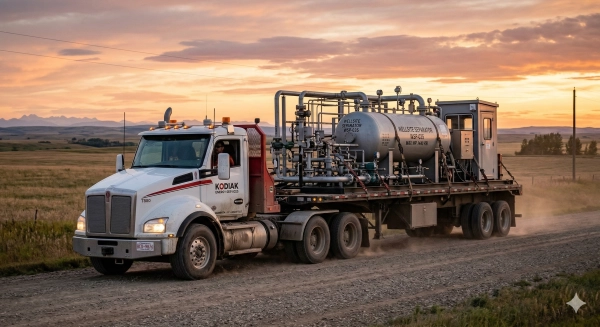
Trailer-Mounted
Trailer-mounted separators prefer quick moves between dispersed wellheads, brief test windows, and distant roads. Crews can arrive, level, connect, and start in hours, minimizing standby and capturing early-time flow behavior.
Most packages ship with integrated manifolds, valves, instruments, and control panels wired and pressure tested, so operation is plug and play. Select flowmeters by design pressure and fluid mix. Coriolis with EGM assists when slugs or foam push gas into liquid legs. Trailers comply with road rules, axle loads, braking and lighting codes, and equip off road clearance, mud guards, and tie downs for tough leases. This is superior where frequent relocations beat downtime. Multi well appraisal programs, step rate tests, short clean ups, and rapid diagnostic surveys occur across fields.
Build a simple decision matrix: rows for mobility, set-up time, pad space, capex/opex, data quality risk, pressure class; columns for skid versus trailer; score by project requirement.
Why Expert Partners Matter
Expert partners set the standard for test separator design, construction and on-site application. They provide process design, metering and safety expertise that reduce risk and accelerate delivery while making costs transparent and manageable.
Partner with experienced equipment providers to access high-quality, fully compliant test separator packages tailored to your needs.
Industry leaders understand what applies to pressure vessels, flares and custody transfer. They tie designs to ISO and API good practice and align with local codes. You get the right pressure class, proper phase handling and certified measurement in one convenient package. That translates to fit-for-purpose internals, right-size valves, dependable temperature and pressure gauges, and flow meters with known uncertainty. Partners customize skid footprints for tight pads, provide winterization for cold sites and construct for rapid rig-up with defined lift points and optimized pipe runs. Their networks provide connectivity to new level sensors, real-time multiphase meters, and data links that flow to your SCADA. That brings in options without long lead times and keeps your project on schedule.
Rely on expert support for equipment selection, installation, commissioning, and ongoing maintenance.
Selection support begins with your test objectives—flow range, gas-oil ratio, water cut, H2S, sand load and power constraints. Experts map these to separator size, control schemes and meter choice. At install, they direct spool drawings, tie-in heights and vent routing, so site crews steer clear of rework. At start-up, they conduct leak checks, instrument loop tests, prover runs and baseline data grabs to cement accuracy. After handover, they establish no-nonsense service schedules, stock essential spares and train operators. This fosters a learning culture on site and maintains uptime. Their candor highlights the risks that can take a process or product down early—slugging risk, foaming or wax—so interventions arrive before it shuts down.
Benefit from proven track records in delivering reliable, accurate measurement and safe separation under Alberta oilfield conditions.
Alberta brings icy, sour gas and red tape. Veteran teams on this front design heat tracing that functions at minus 30 degrees Celsius, select elastomers that resist H2S and optimize relief sizing for actual blowdown scenarios. They choose meters that maintain precision across broad turndown and sand. They display third-party audits, calibration logs, and incident-free hours, which cultivates trust with regulators and investors. They get everyone—operators, service crews, labs—on the same page so data is clean and reportable.
Encourage operators to prioritize expertise and service quality when sourcing test separators for critical well testing operations.
Require previous jobs with similar fluids and flows, evidence of metering uncertainty, start-up plan and local spare parts inventory. Look for training options, round-the-clock support lines, and escalation channels. Prefer teams that pass on lessons learned and welcome peer reviews. This creates shared knowledge, quicker solutions and eventually, entry into new sectors and customers via enhanced reputation.
Conclusion
A solid test separator plan can be summarized to fit safety and cost. Choose the appropriate size for your flow rates and gas-oil ratio. Match pressure limits to your wells. Set goal test time, data range, and site limits. Test with actual field data, not wishful charts. For Alberta locations, pay attention to road bans, sour gas regulations, and cold starts. Account for crew needs and rig-up time. Select mobile units for short projects or spaced-out pads. Select block units for extended periods of steady stream.
To go quick, map your wells, identify your data gaps and price two setup paths. Time for a gut check? Provide us your site information, flow rates and test objective. I can assist in sketching out a simple and concise course of action.
Frequently Asked Questions
What is a test separator and why is it used?
A test separator is a vessel system used temporarily to separate the oil, gas, water, and solids from a well stream. It measures flow rates and fluid properties. Operators employ it to confirm well performance, optimize choke configurations, and safely plan production.
How do test separators work?
They use a pressure drop and phase separation. Within the vessel, fluids decelerate, enabling gas to disengage and liquids to drop out. Internal baffles, mist extractors and weirs enhance separation. Meters and sensors log rates, pressures and temperatures for precision well testing.
What criteria should I use to select a test separator?
Match pressure rating, temperature, anticipated gas-oil ratio, water cut, and solids load. Think measurement accuracy, regulations, and footprint. Assure materials compatibility and safety systems. Select validated setups with calibration certificates and maintenance logs for dependable results.
What are common types of test separators?
Typical ones are two-phase (gas-liquid), three-phase (oil-water-gas), and horizontal or vertical. Some units are high-pressure or sour-service rated. Skid-mounted and trailer-mounted options enable rapid deployment. Inline multiphase meters can supplement or take the place of separators on certain occasions.
What should operators in Alberta consider?
Consider provincial regulations, sour gas (H2S) hazards, cold-weather operations, and site access. Adhere to AER guidelines when measuring and flaring. Winterization, good materials, and emissions controls are important. Compliance documents and calibration traceability are necessary before mobilizing.
When should I choose a mobile test separator?
Go mobile when you want rapid deployment, short test windows, or multi-wells on a pad. Mobile units minimize downtime and shipping expenses. They are perfect for flowback, DST, and early production where flexibility and swift demobilization are important.
Why work with expert partners for well testing?
Specialists take out risk and enhance data. They properly size the unit, safely manage sour service and guarantee compliance with codes. They offer professional crews, calibrated meters and immediate troubleshooting. That means quicker decisions, safer operations and less total cost.
Looking for more oilfield equipment insights? Browse additional resources from Benoit Rentals Ltd about test separators, support equipment used across Alberta and Saskatchewan.
Oilfield Tank Rentals and Sales
Want to learn more about oil and gas production processes and equipment used in well testing? Explore these trusted resources:
Alberta Energy Regulator – Oil and Gas Regulatory Information