- Key Takeaways
- What is a Burner Management System?
- How a Burner Management System Functions
- Core BMS Components
- Mitigating Critical Oilfield Risks
- Navigating Alberta’s Regulatory Landscape
- The Human Element in Automated Safety
- Train operators to understand and interact effectively with BMS technology
- Encourage routine system checks and maintenance to supplement automated safety
- Foster a safety-first culture by integrating human oversight with automation
- Empower personnel to respond quickly to alarms and system prompts for enhanced protection
- Conclusion
- Frequently Asked Questions
- What is a burner management system (BMS)?
- How does a BMS work during startup and shutdown?
- What are the core components of a BMS?
- How does a BMS improve oilfield safety?
- Is a BMS required by regulations in Alberta?
- How often should a BMS be tested and maintained?
- Can operators override BMS safety functions?
Key Takeaways
- A burner management system is an auto safety control that manages start-up, operation, and shutdown to avoid fires and explosions while facilitating standard compliance. It connects to site systems for centralized monitoring and control.
- Safe operation goes through a sequence from pre-purge to post-purge with automated checks minimizing human error. Continuous monitoring and fail-safe shutdowns react to abnormal conditions to safeguard personnel, machinery, and the environment.
- At its core are sensors, a logic solver, actuators and an operator interface, all providing reliable detection, decision-making, action and visibility. This type of coordinated component integration and routine maintenance is a hallmark of the burner management system style of control.
- Apply best practices that enforce strict burner sequences, verify purge durations, and test flame detection and shutdown functions. Keep accurate logs for troubleshooting, performance analysis, and audit readiness.
- For regulated regions such as Alberta, align configurations with applicable codes, document inspections, and track updates to maintain compliance. Regular internal audits and gap assessments help ensure systems meet or exceed current requirements.
- Bolster the man in the loop with training, drills, and transparent alarm response processes. In addition to automation, schedule regular functional tests and inspections to maintain a safety-first culture.
A burner management system is a control and safety system that initiates, controls and shuts down industrial burners to reduce the risk of fire, explosion and fuel wastage. It monitors critical parameters such as flame signal, fuel pressure, air flow and purge status, then performs control logic to permit secure light-off and maintain stable operation. Designed to comply with codes like NFPA 85 and EN 746-2, it frequently utilizes a PLC or a certified safety controller with SIL-rated components. Standard features are flame scanners, purge timing, interlocks, trip logging, and manual or auto mode. Most configurations interface with a DCS or SCADA for alarms and trends. The following sections describe the underlying components and logic steps, outline code requirements and best practices for testing.
What is a Burner Management System?
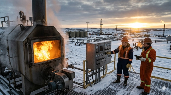
A burner management system (BMS) is an automated safety device that controls start-up, normal firing, and shutdown of industrial burners used in oilfield heating and other thermal processes. Think of it as the frontline against unsafe combustion, minimizing the risk of fires, explosions, and unplanned trips. It supports sites in achieving safety standards and complies with operating rules by enabling pre-firing and ongoing firing checks and recording events for audit purposes.
A BMS gives automatic oversight when equipment is online. It monitors critical conditions such as valve openings, air flow, pilot flame, and main flame. If some bad unit conditions happen, such as loss of flame, low fuel gas pressure, blocked air, or high furnace pressure, it performs a Master Fuel Trip (MFT). An MFT closes all fuel valves quickly and in the proper sequence to eliminate heat input and prevent escalation. Think of a dehydrator heater, crude tank heater, or process heater. When a flame-out happens, the BMS closes fuel within milliseconds and forces a safe state before any re-light.
Safe start-up is secured by permissive interlocks. A BMS will not permit light-off unless critical checks pass, like proven airflow, valve line-up, pressure ranges, instrument health, and more. It inhibits firing until a complete furnace purge is finished, removing unignited fuel from the firebox using defined airflow for a defined time, typically based on volume and flow, such as multiple air changes in cubic meters per second. These steps reduce the chance of late ignition and minimize fuel accumulation.
BMS designs use two main methods: separated or integrated. In a separated architecture, an SIS manages safety logic and trips, whereas a BPCS manages temperature and flow control. This split adds independence. If one hardware path fails, the other stays functional. It fits more risky services or compliance-heavy cases. An integrated BMS merges safety and control on one platform, leveraging certified logic solvers and segregated software. It can reduce shutdown time, simplify tie-ins to valves and analyzers, and reduce hardware and installation costs, benefiting remote pads or small skids. Regardless, the BMS integrates with site PLCs, SCADA, historians, and alarm systems for centralized monitoring, cause-and-effect displays, and safe change control across hundreds of burners and units.
How a Burner Management System Functions
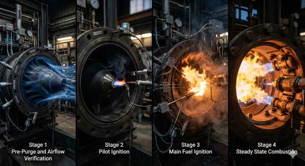
A burner management system (BMS) reduces critical safety hazards in industrial firing by automating safety interlocks and managing fuel input throughout the entire burner cycle. It operates in automatic or supervised manual modes, applies safety interlocks, and is sometimes separated from BPCS or integrated. Standards like NFPA 85 direct purge times, interlocks, and test routines. Typical steps include: 1) pre-purge, 2) permissives verified, 3) ignition trial, 4) flame proven, 5) normal operation, 6) normal shutdown or emergency trip, and 7) post-purge. Automation eliminates human error and continuous sensing and fail-safe design backstop abnormal events with a Master Fuel Trip (MFT).
1. Pre-Purge
The BMS initiates purge to scour the furnace and flue paths with fresh air, sweeping residual fuel gases in advance of any spark. Purge air volume and time satisfy NFPA 85 and local codes, usually based on a number of air changes linked to chamber size in cubic meters.
Airflow switches and differential pressure sensors verify fans, dampers, and stack paths are open and venting. If airflow is low or a damper is closed, the BMS suspends the sequence. Fuel valves remain closed and ignition is inhibited until purge permissives are met.
2. Ignition Trial
Following a successful purge, the BMS opens the pilot fuel valve, energizes the igniter, and times the trial-for-ignition window. It controls pilot gas and spark power to ignite quickly and cleanly.
If flame is not proven during the defined seconds, the system locks out, records the attempt and requires a new purge before retrying. Repeated failures trigger maintenance checks.
3. Flame Detection
Flame scanners (UV, IR, or ionization) monitor for a steady flame signal. When the flame drops during firing, the BMS performs MFT, closes all fuel, and initiates post-purge.
Signal processes filter out noise, burner front reflections, and hot refractory to prevent false positives. All flame data and trips are time-stamped for audits and tuning.
4. Normal Operation
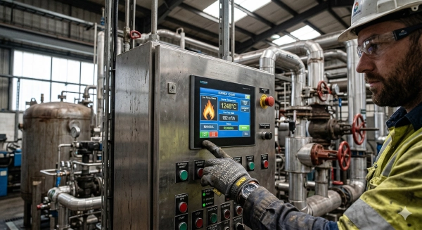
The BMS energizes fuel valves, pilots, and limit switches, with the control loop trimming air and fuel with feedback from oxygen, pressure, and temperature sensors.
It alerts abnormalities like low gas pressure, fan failure, or quick temperature rise. Operators see status on HMI screens and can choose auto or supervised manual. Safety interlocks still impose restrictions. In unsafe conditions, the BMS sends an MFT and goes to a safe state.
5. Post-Purge Shutdown
For an orderly shutdown, fuel closes and fan runs to vent residual gases, and airflow is proven before entry is permitted. For an emergency shutdown, MFT does first. Then post-purge clears the trail.
The BMS logs shutdown type, cause, and duration for compliance and trend work. Restart is inhibited until post-purge and all permissives pass.
Core BMS Components
Core BMS Components
A Burner Management System (BMS) monitors firing equipment in operation, prevents start-up until permissive interlocks are satisfied, initiates a full purge, and performs a Master Fuel Trip (MFT) on fault conditions to safeguard personnel, assets, and availability. Integration across components is crucial for rapid, auditable action that complies with NFPA 85 and IEC 61511.
| Component | What it does | Why it matters for safety and reliability |
|---|---|---|
| Sensors | Measure flame, temperature, pressure, and gas flow | Catch unsafe states early and feed clean data to logic |
| Logic Solver | Runs sequences, checks permissives, and triggers MFT | Enforces safe states, consistent start/stop, and compliance |
| Actuators | Move valves and dampers; double-acting valves common | Precise, fast energy isolation and air/fuel control |
| Interface | Shows status, alarms, and trends; manages access | Clear decisions, secure changes, and audit-ready records |
Sensors
Sensors monitor temperature, pressure, gas flow, and presence of flame to simulate actual furnace and fuel-line conditions. UV/IR flame scanners ensure stable combustion and differential pressure transmitters validate purge air flow prior to light-off.
They feed real-time values to the logic solver for split-second decisions, like cutting fuel if the flame goes out or a low gas pressure trip occurs. This backs up the MFT operation in case of unfit firing conditions.
Trend data reveals drift and fouling. Between those extremes, a slow-shifting thermocouple or a noisy flow signal can flag a failing probe, helping plan maintenance before faults block a start. Keeping the transmitters calibrated and purging the lines clean reduces these spurious trips.
Logic Solver
The logic solver reviews inputs, verifies permissives, and only then allows ignition. If purge is incomplete or an interlock is open, the BMS prohibits start-up.
It executes start-up, operation, and shut-down protocols, including purge timing, pilot prove, main flame prove, and tight-shut fuel isolation at stop. In unsafe states, it generates alarms or an MFT to close all fuel valves immediately.
Cached event logs, time-stamped excursions, and sequence reports support root cause analysis and compliance audits.
Actuators
- Core BMS components are snap closed double block-and-bleed fuel valves on MFT.
- Modulating air dampers retain excess O2 under load swings.
- We stroke double-acting gas valves for tight shutoff and quick reopening.
- Drive pilot valves during light-off, then close on flame prove failure.
- Locate pneumatic low-pressure valves through thermostats when heat varies.
They have to actuate quickly and with consistent stroke times. Manual overrides enable safe local actions during emergencies. Proof of closure tests, partial stroke tests, and stroke time checks keep performance tight.
Interface
Operators view real-time status, permissive states, purge timers, and alarm priorities. Transparent color and writing designate regular and irregular status to reduce fault hazard.
Protect roles gate setpoint edits and manual controls, minimizing unauthorized modification. Logs, trends, and reports display MFT causes, valve proof results, and sensor health for transparency and compliance.
Mitigating Critical Oilfield Risks
Burner management systems (BMS) mitigate risks associated with fired equipment by managing fuel, ignition, and purge stages. They are most effective when paired with a process hazard analysis (PHA). If the PHA misses BMS functions or existing safeguards, teams can overlook key hazards or misjudge risk severity.
Checklist: Do’s and Don’ts of burner management
- Yes, confirm that the BMS scope corresponds to the specific hazards in every heater, boiler, or reboiler, not a sample form.
- Yes, align safety targets to IEC 61508/61511. Use a SIL-capable logic solver when risk reduction objectives require it.
- YES, use NFPA 85 for units greater than or equal to 12.5 million BTU per hour and ASME-CSD1 for smaller units. Document any gaps and explain variances.
- Separate BMS from basic controls where required to prevent common cause trips.
- Conduct test flame detection, purge logic, tightness tests, and valve proof checks on a prescribed schedule with documented procedures.
- Log every start, trip, bypass use, and alarm with time stamps for traceability.
- Don’t depend on manual inspections where automated proof tests are possible.
- Don’t jump over interlocks without a permit, a time limit, and management sign-off.
- Don’t assume BMS covers risks like tube rupture and loss of draft. Check in design and PHA.
- Don’t be cavalier about risk in startups. Use checklists to prevent step skips.
Minimize the risk of explosions and fires by implementing burner control sequences. A good BMS performs purge, light-off, main fuel admit, and modulation in a fixed sequence. It prohibits fuel flow until purge volume and time are achieved, prevents re-light following flame failure without a purge, and cuts off fuel on low air, low fuel gas pressure, high furnace pressure, or pilot loss. Automated BMS on direct and indirect fired vessels promote reliable startups and reduce human error, enhancing dependability and uptime.
Allow quick system turn off upon detecting abnormalities. Fast-acting, de-energize-to-trip fuel valves and independent flame scanners permit instantaneous trips on hazardous conditions. Tie-in to plant ESD allows one command to shut several burners. A performance-based approach, like API practices borne from ISA 84/IEC 61511, can establish unambiguous trip criteria that have flexibility but must be site-specific to risk and proof-test intervals.
Back incident investigation with operational records. Save event logs, alarm histories, bypass records, and proof-test results. Granular time stamps assist in reconstructing sequences, verifying SIL targets, and refining PHAs. Good records illuminate nuisance trips, confirm maintenance, and direct training.
Navigating Alberta’s Regulatory Landscape
Alberta’s approach to managing burner management systems (BMS) is regulated through a combination of provincial regulations and referenced national and international standards. The framework covers oil and gas, power and industrial heat processes; hence, standards vary by fuel type, equipment category and risk. They set the bar. Performance-based routes allow engineered solutions as long as they meet or exceed safety goals.
| Alberta / Referenced Code | Core Requirement | Implications for BMS |
|---|---|---|
| Alberta Gas Code (adopts CSA B149 series incl. B149.3) | Approval of fuel trains and control assemblies; certified components; safe startup/shutdown; lockout on fault | Use listed valves, regulators, and flame safety; prove purge, ignition trials, and interlocks; maintain approvals |
| CSA B149.3 (Code for field approval of fuel-related components on appliances) | Field evaluation of modified/assembled fuel trains, leak checks, combustion safeguards, documentation | Provide wiring diagrams, valve proof-of-closure tests, flame failure response of one second or less (as applicable), tag-and-trace components |
| NFPA 85 (Boiler and Combustion Systems Hazards Code) | Boiler and multi-burner combustion safeguards | Configure purge volumes, master fuel trip and burner-permissive logic, prove airflow and fuel pressure | API 556 (Instrumentation for Fired Heaters) | SIS architecture, sensor voting, separation from basic controls | Design independent BMS layers, apply 2oo3 where risk warrants, segregate power and I/O | | ISO 13577-2 (Industrial furnaces and thermal processing equipment) | Safety requirements for firing systems, purge, ignition, flame control | Establish purge rates per volume, reliable flame detection, safe state on loss of utilities | | AS 3814 (Gas-fired appliances – industrial/commercial) | Safety controls for gas appliances | Good benchmark when equipment is imported, match trip, purge, relight logic to Alberta approvals
Get BMS configurations that are provincially mandated or above. Map each BMS function – purge, light-off, flame monitoring, trips, resets – to the applicable clause, then verify it during a site acceptance test. For example, check purge time against actual furnace volume in cubic meters, not vendor default. Test double-block-and-bleed valve tightness with proof-of-closure switches. Isolate safety logic from process control so a PLC fault fails the system to a safe state. If they are in doubt, follow the tougher rule – CSA B149.3 or NFPA 85.
If nothing else, keep records for regulatory inspections and audits. Keep a controlled dossier: P&IDs, cause-and-effect, SIL/LOPA records, device data sheets, wiring diagrams, factory and site test records, calibration logs, management-of-change forms, and operator procedures. Store with revision control for the asset life.
Keep ahead of changing regulations to ensure continued compliance. Bulletins from Alberta authorities, CSA amendments, and changes to NFPA 85, API 556, and ISO 13577-2 are important. Plan annual code gap checks, re-test safety functions following any change, and train operators and technicians on new setpoints and steps.
The Human Element in Automated Safety
Burner management systems (BMS) reduce risk by automating ignition, flame monitoring, purge, and shutdown. They still depend on humans to set boundaries, maintain the equipment, and interpret information with nuance. Good safety arises from a transparent connection between what the system does and what people do in response.
Train operators to understand and interact effectively with BMS technology
Operators need hands-on drills that mirror real plant states: cold start after maintenance, low fuel pressure at 300 kPa, flame failure during light-off, or loss of instrument air. That includes logic steps, interlocks, trips, and bypass rules, as well as reading trends like rising stack oxygen, slow flame instability, or repeated light-off faults. One such tool is to use simulators and fault trees so teams practice responses to alarms, not guess. Manual systems that many sites used for decades often lack precision, drift with wear, and do not auto-reignite. That gap demonstrates why humans need to grasp when to rely on auto sequences and when to pause, clean, and re-validate.
Encourage routine system checks and maintenance to supplement automated safety
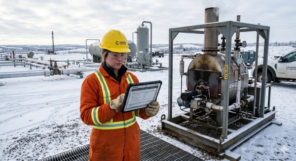
Automated safety can reduce human error. It relies on maintenance. Schedule monthly proof tests of flame scanners, pressure switches, and valve stroke times. Record response in milliseconds, not ‘pass/fail’. Calibrate sensors with traceable meters. Check wiring for thermal damage. Check alarm history to identify nuisance alarms that condition users to disregard real ones. Remember that maintenance is time-intensive and can introduce its own error. Employ checklists, peer sign-off, and lockout tags. Stock igniters, relays, and gaskets on-site to reduce downtime and last-minute repairs.
Foster a safety-first culture by integrating human oversight with automation
Design the HMI to fit human factors: clear alarm priority, plain language, color use that supports color-blind users, and limits on alarm floods. Establish guardrails to avoid unsafe bypasses and shift handover notes. Combat fatigue and distraction through staffing plans, quiet panels, and short alarm drills near shift change. Construct blameless, learning-oriented post-mortems.
Empower personnel to respond quickly to alarms and system prompts for enhanced protection
Determine alarm setpoints with reason and link each to a 1-page action card. Train fast checks: verify fuel valves are closed, confirm purge flow is above the minimum in m³/h, and recheck permissives before re-light. Leverage BMS data for root cause analysis and always complement it with field checks – listen for valve chatter, sniff for leaks, and verify flame viewports are clean. Automated systems bring critical data to the surface. Humans evaluate intent and how to proceed. Smart systems minimize human error, but they need to be constructed and operated with humans in the loop to provide a resilient safety architecture.
Conclusion
A bang-up burner management system slashes hazard, slices downtime, and keeps the heat hitting its mark. Sensors monitor flame, fuel, air, and purge. Logic trips immediately on fault. Valves close. Alarms identify obvious faults. That combo creates a safer site and a cleaner burn.
Field crews still established the rhythm. Well-laid plans, straightforward drills, and cool calls bring out the glow in gear. Regulations in Alberta establish the minimum standard. Proof tests, logs, and trained techs keep you in line and ahead of audits.
To move next, map your heat loads, gas quality, and trip setpoints. Pick SIL needs. Match hardware to the site. Set a test plan with dates. Train the shift. Start with one unit, learn fast, then scale. Need a hand? Reach out for a quick site review.
Frequently Asked Questions
What is a burner management system (BMS)?
A BMS, or burner management system, is a safety control for industrial burners. It inhibits unsafe startups, detects flame status, controls fuel valves, and performs safe shutdown. It lowers fire, explosion, and emissions risks while assisting compliance with regulatory demands.
How does a BMS work during startup and shutdown?
It executes interlock checks, purges the combustion chamber, ignites the pilot, validates flame, and opens main fuel valves. If a fault is detected, it closes fuel valves and initiates a safe shutdown. It logs events for troubleshooting and compliance.
What are the core components of a BMS?
Key components are flame scanners, safety PLC or relay logic, fuel shutoff valves, pressure and temperature sensors, purge controls, pilot ignition systems, and HMIs. Each one checks safe conditions and triggers fail-safe actions.
How does a BMS improve oilfield safety?
It senses flame failure, gas leaks, insufficient airflow and irregular pressure. It shuts fuel valves in milliseconds and sounds alarms. This minimizes explosion hazard, equipment damage and downtime. It further facilitates safer maintenance and startup.
Is a BMS required by regulations in Alberta?
The majority of fired equipment would have to adhere to Alberta requirements and such standards as CSA B149.3 and NFPA 86. Tests, proof-of-closure, and purge cycles need to be recorded by a competent person for design, commissioning, and compliance.
How often should a BMS be tested and maintained?
Depending on the application type, some functional tests should be performed at defined intervals: often monthly for flame failure and valve tightness and annually for full system proof tests. Listen to the manufacturer’s instructions, site risk policies, and local codes. Maintain audit records.
Can operators override BMS safety functions?
Overrides should be strictly controlled and temporary. Most codes limit or prohibit bypassing safety interlocks. Any bypass requires documented risk assessment, permits, supervision, and immediate restoration. Safety functions must default to fail safe.
Not the topic you were searching for? Visit more resources from Benoit Rentals Ltd to learn about oilfield equipment rentals, power systems, containment solutions, and production support services.
Oilfield Tanks Rentals and Sales
For more background on natural gas, production equipment, flare system used in oilfield facilities, consult these trusted references:
Oil Production Equipment and Separator Technology Overview